Average-Value DC-DC Converter Control - MATLAB & Simulink
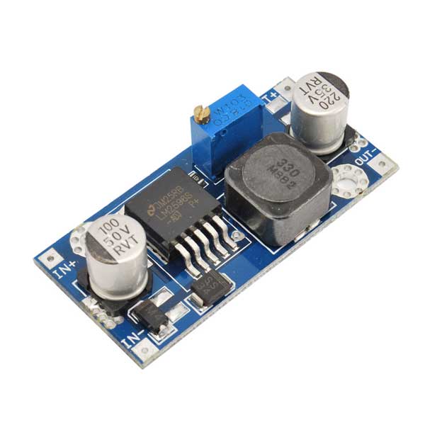
€ 28.50 · 4.6 (513) · In Magazzino

This example shows how to control the output voltage of a buck-boost converter.
Control the output voltage of a buck-boost converter. To adjust the duty cycle, the Control subsystem uses a PI-based control algorithm. An average-value DC-DC converter model is used to speed up the simulation. The input voltage and the system load are held constant throughout the simulation. The total simulation time (t) is 0.25 s. At t = 0.15 s, the voltage reference changes and the system switches from buck mode to boost mode.
Highlight, take notes, and search in the book In this edition, page numbers are just like the physical edition

Average Current-Mode Control of DC-DC Power Converters

Simulation of Power Converters Using Matlab-Simulink

Review on non-isolated DC-DC converters and their control techniques for renewable energy applications - ScienceDirect
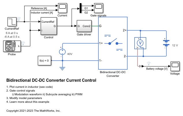
Bidirectional DC-DC Converter Current Control - MATLAB & Simulink - MathWorks France
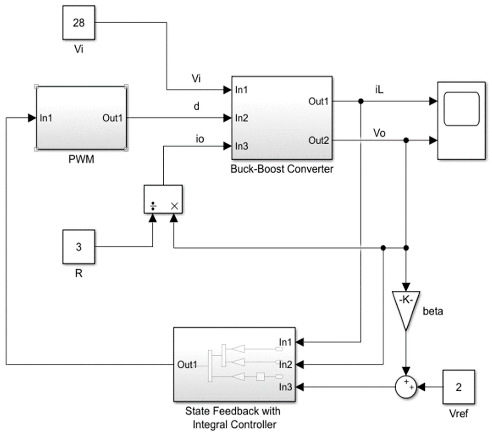
Mathematics, Free Full-Text

Simulation of Power Converters Using Matlab-Simulink

Simulink boost converter problem - Electrical Engineering Stack Exchange

Review on the Digital Control Laws for the High-Frequency Point-of-load Converters

Voltage Control Design How to Develop DC-DC Converter Control in Simulink, Part 4 - MATLAB & Simulink
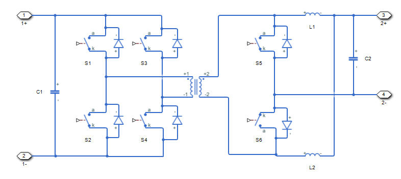
Controller-driven bidirectional DC-DC step-up and step-down voltage regulator - MATLAB
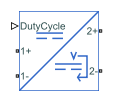
Average-value DC-DC converter - MATLAB

Two-Phase DC-DC Converter Current Control - MATLAB & Simulink

Closed Loop Control of a DC-DC Buck Converter - MATLAB & Simulink

Converters (Low power) - MATLAB & Simulink - MathWorks Italia